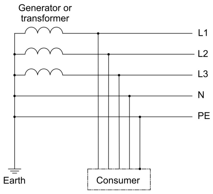
There are several different types of medium voltage earthing systems. These systems can be differentiated by using the neutral point connection method. They are different in the way that they operate and each of them has its own pros and cons. These earthing systems in medium voltage include the likes of:
- Unearthed neutral
- Directly earth neutral
- Reactance earthing
- Resistance earthing
- Petersen coil earthing
The functioning of each differs from the other. They also have various applications. Let’s have a look at each system at a time:
- Unearthed neutral:In this one, there is no electrical connection between the earth and the neutral point except for the devices that are used for measurement or protection. There is high impedance inserted between the earth and the neutral point. There is no switching on occurrence of the first insulation fault. It is therefore important to carry out permanent insulation monitoring, show the first insulation fault and locate and clear the first insulation fault.
Pros and cons: The advantage of using this one is that it provides services by tripping only when the second fault occurs which is subject to the capacity of the network not leading to a high earth fault current which would be dangerous for people when the first fault occurs. It has its demerits. There is the risk of high internal over-voltages. Insulation monitoring is also compulsory as well as the presence of maintenance personnel who will be monitoring and locating the first fault during use. - Direct earth neutral:It is also known as direct earthing. It has a connection between the earth and the neutral point. Upon first insulation fault occurrence compulsory switching must be done. It is significantly different from the above mentioned unearthed neutral.
Pros and cons: This system reduces risk of over-voltage occurring and also authorizes the use of equipment with a normal phase to earth insulating level. On the other hand, there is mandatory tripping upon occurrence of the first fault. The touch voltages developed are very high and this poses a high risk for the personnel while the fault lasts. Differential protection devices must be used so that the clearance time of the fault is as short as possible. - Resistance earthing: This system requires a resistor to be inserted between the neutral point and the earth. It is also known as limiting resistance earthing. Their operating technique is quite straightforward. Switching must be done upon the occurrence of the first fault.
Pros and cons: It limits fault currents which reduces damage and disturbances. It also keeps over voltages arising from within the system. It does not require special equipment and specifically cables that have a special phase-earth insulation level. Simple selective protection devices can be used. The major disadvantage of this system is that tripping occurs upon the first fault occurrence. - Reactance earthing: Also called limiting reactance earthing, reactance earthing has a reactor which is inserted between the earth and the neutral point. Upon the first insulation fault switching has to be done. It is almost similar to the resistance earthing.
Pros and cons: It limits the fault currents thus reducing disturbance and damage. Since a low resistance coil is used, it does not dissipate a high heat load. It however can cause high over-voltages during clearance of earth fault. There is also compulsory tripping when the first fault occurs. - Petersen Coil Earthing: In this earthing system, a reactor L which is tuned to the network capacities is inserted between the earth and the neutral point. In case an earth fault occurs, the fault current is zero. There is no switching upon occurrence of the first fault.
Pros: If the phase-earth fault current is kept at zero then the benefits to be enjoyed are many. For starters, there is spontaneous clearance of the non-permanent earth faults. In spite of a permanent fault existing, the installation will continue operating. Tripping occurs on the second fault. If current is detected flowing through the coil then this is an indication of the first fault.
Cons: There is a high risk of over-voltages occurring and it also requires the presence of monitoring personnel. It is impossible to provide selective protection upon occurrence of the first fault essentially if the coil is tuned to 3 L0 C0 W2 = 1. Establishing this condition is also difficult due to uncertain knowledge of the network’s capacity. There is also the risk of ferro-resonance.
D&F Liquidators has been serving the electrical construction materials needs for more than 30 years. It is an international clearinghouse, with 180,000 square facility located in Hayward, California. It keeps an extensive inventory of electrical connectors, conduit fitting, circuit breakers, junction boxes, wire cable, safety switches etc. It procures its electrical materials supplies from top-notch companies across the globe. The Company also keeps an extensive inventory of electrical explosion proof products and modern electrical lighting solutions. As it buys materials in bulk, D&F is in a unique position to offer a competitive pricing structure. Besides, it is able to meet the most discerning demands and ship material on the same day.


