Table of Contents
What do street lamps, data centres, and stadiums have in common? They all need a lot of electricity.
However, getting electricity for these uses isn’t as simple as just connecting to power lines. The electricity in power lines is very high voltage, which is only good for sending power over long distances. To be used in everyday applications, electricity has to go through a transformer, which changes it to a suitable voltage.
Many people recognize a transformer when they see one, but understanding how it works is different. Whether you’re planning to buy a transformer or set one up, knowing what transformers do and how they operate can help. This article introduces you to transformers, explains why we need them, how they work and goes over their key parts.
What are Electric Transformers?
Electric transformers are devices that transfer electric power from one circuit to another without changing the frequency. They can increase or decrease voltage, which corresponds to a decrease or increase in electric current. The operation of electric transformers relies on electromagnetic induction and mutual induction principles.
How Do Electric Transformers Work?
Transformers follow a rule called the law of energy conservation, which says energy can’t disappear, it can only change form. So, transformers don’t make electricity, they just adjust how strong it is to fit what’s needed.
Transformers do this by using something called Electromagnetic Induction.
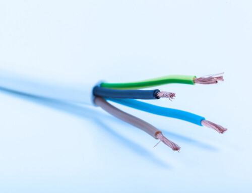
When you run electricity through a wire, it creates an invisible magnetic field around the wire. If you put another wire near this field, the changing magnetic field makes electricity flow in the second wire.
You can use this process to make the voltage higher or lower between the two wires. You do this by wrapping the wires into coils, with one coil having more loops than the other. When you send electricity through the coil with more loops, it makes electricity flow in the other coil at a different voltage.
Parts/Components of Electric Transformers
-
Bushings
Transformer bushings are insulated components that enable electricity to pass through the tank wall of a transformer without direct contact. They connect the transformer to the power source on the high-voltage side and to the load on the low-voltage side, ensuring safe and efficient electrical transmission.
-
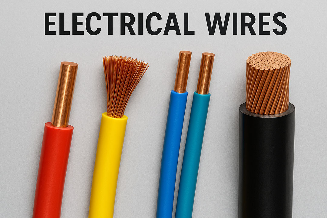
Core & Coils
The core and coils form the essential parts of a transformer where the induction process occurs. When electricity flows into the transformer, the coils determine how the voltage is transformed. These coils, wrapped around the core, can be made from aluminum or copper, and are crucial in managing the voltage conversion.
-
Load Break Switches
Load break switches (LBOR switches) are special rotary switches that allow electrical workers to manually disconnect the transformer from the power grid. These switches can be operated even when the transformer is under load, de-energizing the core and coils for safe maintenance and operation.
-
Fuses
Transformer fuses play a critical role in safeguarding the electrical system against potential issues within the transformer or downstream equipment. When subjected to high currents or excessive heat, a thin wire known as an “element” melts, interrupting the flow of electricity and isolating the transformer from the power grid.
-
Voltage Adjustment Taps
Voltage adjustment taps in transformers ensure the maintenance of the correct secondary voltage, compensating for variations in primary voltage levels. By rotating the tap changer, segments of the primary windings are adjusted, modifying the ratio of primary to secondary windings and regulating the primary voltage.
-
Fluid
Transformer oil or fluid serves as a vital cooling agent to dissipate heat generated during transformer operation. Stored in a specialized tank, the fluid circulates through channels between the transformer windings, functioning as both an insulator and coolant. It is exclusive to liquid-filled transformers.
-
Gauges
Transformer gauges are instrumental in monitoring various operational parameters, such as oil level, temperature, and tank pressure. In larger transformers, monitoring systems may offer more comprehensive and sophisticated monitoring capabilities to ensure optimal performance and safety.
Types of Electric Transformers
-
Iron Core Transformers
Iron core transformers are known for their high efficiency due to the presence of multiple iron plates with excellent magnetic properties. The rapid magnetization and demagnetization process in these transformers make them a preferred choice. Typically, the iron plates are made of silicon steel with insulating paint to minimize heat effects during operation.
-
Isolation Transformers
While all transformers utilize induction to convert electricity, isolation transformers specifically serve to transfer electrical power from one source to another device. What sets them apart is their primary function of isolating electricity or devices from the power source. Common applications include uninterrupted power supplies, robotics, test and measurement systems, motor controls, and data communication systems.
-
Ferrite Core Transformers
Ferrite core transformers excel in minimizing energy loss in high-frequency applications. Their permeable magnetic properties enable this efficiency. Configured in an E-type arrangement, these transformers can be customized to fit various functions and applications.
-
Step Up Transformers
Step-up transformers are highly efficient devices capable of converting lower voltages into higher voltages while simultaneously reducing amperage and minimizing the effects of resistance. This makes them well-suited for applications such as power transformation and modification. They operate by channeling electrical energy through two phases of coils, with the second coil phase containing a greater number of windings, forming a complete coil assembly.
Some applications of step-up transformers require a single set of windings, while others necessitate a tertiary set. These transformers typically consist of two sets of coil windings wrapped around a core made of either a ferrite compound or laminated material. The coil windings are often constructed from aluminum, nickel, copper, chromium, and steel alloys, maximizing energy efficiency.
-
High Voltage Transformers
High-voltage transformers are essential for altering the voltage of power lines in contexts requiring high-voltage transmission. They are specifically designed to handle voltages ranging from 600 to 5000 volts, where a volt represents the measure of electromotive force. These transformers find applications in metering and providing protection in high-voltage circuits, particularly in industrial and scientific settings.
-
Toroidal Core Transformers
Toroidal core transformers feature a distinctive donut shape that minimizes induction leakage, resulting in high inductance within the system. They are characterized by shorter windings and lighter weight compared to other transformers of similar ratings. However, their manufacturing process is slower, contributing to higher costs.
Benefits & Drawbacks of Electric Transformers
Benefits of Electric Transformers
Electric transformers offer a cost-efficient way to transmit and isolate voltage, making them dependable and budget-friendly. Their flexibility allows for various uses; for example, current transformers are handy for reducing currents in measurement instruments. Additionally, transformers can be set up in different configurations, serving as either step-up or step-down transformers depending on how they’re installed. Some transformers even have multiple taps on the primary winding to handle different input voltages.
Drawbacks of Electric Transformers
Electric transformers need cooling to manage the high temperatures caused by energy losses, which can wear out the insulating materials in the windings faster. They aren’t designed to handle direct current. Maintenance can be tricky, with issues like oil leaks, overloading, and harmonics potentially causing damage, making upkeep quite demanding.
Application of Transformers
Electric transformers are essential components in the world of electricity, primarily used to adjust voltage and current in AC circuits. This basic function serves a wide range of purposes across various industries. Here are some important applications of electric transformers:
Power Transmission and Distribution
Transformers play a vital role in power transmission and distribution:
- Step-up Transformers: These devices increase the voltage from power plants for efficient long-distance transmission, reducing energy loss along the way.
- Step-down Transformers: Near communities, transformers lower high-voltage lines to medium voltage for local distribution.
- Distribution Transformers: Positioned on utility poles or in underground vaults, these transformers further decrease voltage for use in homes and businesses.
Appliances and Electronics
Transformers are integral to many appliances and electronics:
- Power Supplies: They’re commonly found in power adapters and supplies, converting high AC voltage to lower DC voltage for devices.
- Safety Isolation Transformers: Some appliances, especially medical equipment, use transformers to keep users safe from high-voltage electricity.
- Impedance Matching Transformers: Audio equipment often employs transformers to ensure the amplifier and speakers work well together.
Other Applications
Transformers have diverse uses in other areas:
- Industrial Applications: They regulate voltage in machinery, welding equipment, and industrial furnaces.
- Transportation: Electric trains use transformers to convert AC power to the DC needed to run the trains.
- Renewable Energy Systems: In solar and wind power systems, transformers convert DC power from panels or turbines to AC power for use in homes and on the grid.
Frequently Asked Questions (FAQs)
1. Can a faulty transformer cause a high electric bill?
It’s unlikely. Transformers on the power grid adjust voltage, not the amount of electricity you use. Voltage fluctuations from a faulty transformer wouldn’t directly increase your bill.
2. How can electrical energy be transformed?
Electricity can be transformed into many things! Here are some examples:
- Light: Incandescent bulbs use electricity to create light.
- Heat: Appliances like toasters convert electricity into heat.
- Movement: Electric motors use electricity to spin and power machines.
- Sound: Speakers use electricity to produce sound waves.
3. What does an electric transformer do?
An electric transformer changes the voltage and current levels of alternating current (AC) electricity. It uses electromagnetism to increase (step-up) or decrease (step-down) voltage for different uses.
4. What are the different types of transformers?
There are three main types of transformers:
- Power Transformers: These large transformers handle high-voltage electricity transmission between substations and power plants. They can step up or step down voltage depending on the need.
- Step-Up Transformers: These transformers increase voltage, typically used before transmitting electricity over long distances to minimize energy loss. They have fewer turns in the primary coil compared to the secondary coil.
- Step-Down Transformers: These transformers decrease voltage for safe use in homes and businesses. They have more turns in the primary coil compared to the secondary coil, powering electronics and appliances.
5. Can a transformer convert AC to DC?
No, transformers only work with AC. They cannot convert AC to DC (direct current).
6. How is AC converted to DC?
A rectifier is a separate component that converts AC to DC. It uses diodes to allow current to flow in one direction only, changing the AC waveform into DC output. Transformers are often used with rectifiers in AC to DC power supplies. The transformer adjusts the AC voltage, and the rectifier converts it to DC.
7. What are the uses of transformers?
Transformers have two main uses:
- Changing AC voltage levels: This is the most common application. They can be step-up or step-down transformers as explained earlier.
- Providing galvanic isolation: Transformers can isolate circuits from each other while allowing AC signals to pass through. This prevents a direct current path, improving safety and reducing electrical noise.
8. Why are transformers rated in kVA?
Transformers are rated in kVA (kilovolt-amperes) because they deal with apparent power, the total amount of power handled in a circuit. This combines real power (kW) for actual use and reactive power (kVAR) used by motors and inductors, not performing work but adding to the load.
