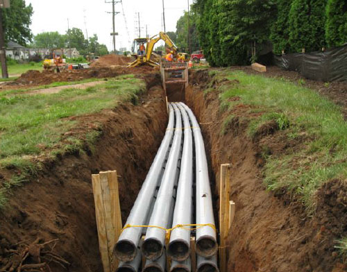
Electrical engineers usually have a huge responsibility in implementing safe electrical conduits to ensure safety and efficiency in designs of power substations. Conduits are the means in which power cables run from the ground to the electrical equipment and appliances.
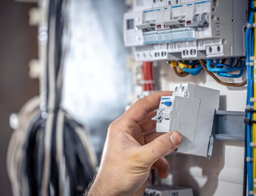
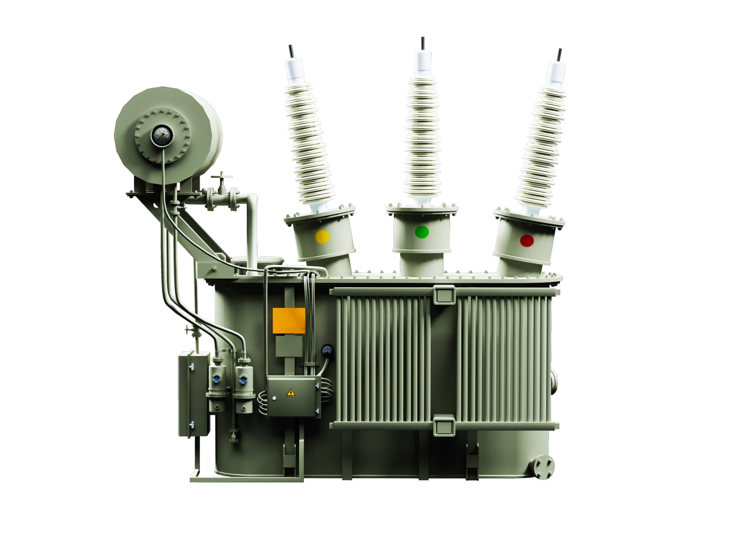
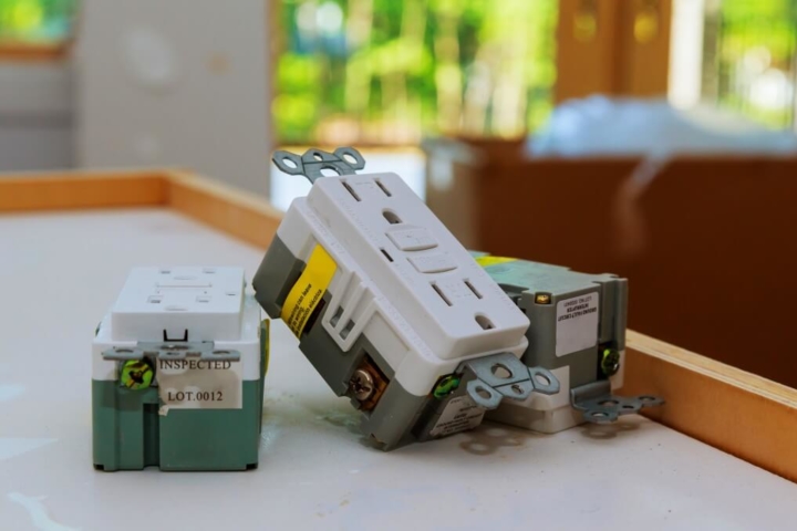
While they can also run to cable trenches, enclosures of electrical equipment and manholes, electricians also use conduits to secure the wiring of electrical cables. The most common use of conduits in power substations is providing access to electrical material, such as transformers, circuit breakers, switches and other electrical instruments in the yard at a substation.
In addition, conduits provide protection of medium-voltage circuits in the power substation. Examples of circuits that need this protection are collector circuits entering the substation and distribution circuits leaving the substation to feed residential and commercial power needs.
Varying types
Conduits come in varying materials and for different uses. For example, there are metallic and nonmetallic conduits. Each of these categories has its own subcategories and classifications. Each conduit fitting has its own pros and cons. The NEC recommends different uses of these types in Articles 342 through 346.
For example, PVC conduits are used widely, thanks to the quality of corrosion resistance. In addition, PVC can be buried underground while concrete is occasionally built over them in buildings.
Design challenges in using conduits
Even with numerous advantages that PVC has, it has its fair share of drawbacks. For example, it is not suitable for use in areas that are prone to physical damage, as the tubing can crack and expose the wires to damage.
In addition, electrical contractors and engineers must contend with the fact that PVC is brittle and prone to damage in cold temperatures. This makes it hard for professionals to work with the material. Maintaining electrical systems in exposed locations of buildings in cold climates is a big challenge.
In addition, the buildup of frost in the power substation yard in northern climates gives engineers a headache. With levels of frost running to four feet deep, heaving causes the frost to pull or push equipment cabinets.
Possible solutions
To solve this problem, electrical engineers can use metal conduit fitting (galvanized steel) to connect above-grade conduit fitting to equipment in the substation yard. Professionals should refer to NEC Article 344 for guidelines on using metal conduits.
A common way of reducing the heaving of conduits into enclosures is the use of expansion fittings. In addition, flexible conduits can reduce the drawback. Correction of local foundation such as the use of a deep sand layer and other site grading practices can eliminate the disadvantage.
If you are an electrical engineer at a substation, consult the State department as far as the requirements for the depth to bury the conduit. In addition, talk to the design engineer at our substation to decide on the type of conduit. Otherwise, it is your role in determining the sizing and routing of the electrical conduits.
Electrical metallic tubing
Usually abbreviated as EMT, this type of conduit is routed in the walls of enclosures of electrical equipment. It can also be used as the principal material for equipment grounding conductor. However, industry experts recommend the running of a separate phase conductor to receptacles and lights within the electrical appliances. The NEC discusses this conduit under Article 358.
In addition, the article outlines how the design should look. It recommends the right cable ampacity de-rating, bending radius, the depth of conduit burial, and calculations on the conduit fill among other features. At the same time, installation considerations such as how to support and secure the conduit are covered.
Typical specifications
The law recommends a depth of 18” for the burial of conduits and cables. However, factors such as frost depth, local laws, conduit bending radius, and cable ampacity should be considered. For example, PVC conduits on circuits of 22kV- 40kV should be at least 24” under the ground. Engineers must also consider the increased depth.
When deciding on the acceptable amount, it is prudent to consider the number of bends that the conduit makes as well as its overall length. In the case of larger underground circuits, electricians can face challenges to apply the industry guidelines.
However, installing conduits larger than 6” for the cable used can solve all problems.
The other challenge is the fact that manufacturers typically produce an 8” PVC conduit while NEC recommends the use of a 6” one. In such cases, the engineer is obliged to discuss with authorities before installing the available conduits.
D&F Liquidators has been serving the electrical construction materials needs for more than 30 years. It is an international clearinghouse, with 180,000 square facility located in Hayward, California. It keeps an extensive inventory of electrical connectors, conduit fitting, circuit breakers, junction boxes, wire cable, safety switches etc. It procures its electrical materials supplies from top-notch companies across the globe. The Company also keeps an extensive inventory of electrical explosion proof products and modern electrical lighting solutions. As it buys materials in bulk, D&F is in a unique position to offer a competitive pricing structure. Besides, it is able to meet the most discerning demands and ship material on the same day.


