One of the biggest challenges faced by electrical engineers, while designing and installing circuitry, is ensuring that electrical fittings can accommodate different plugs. The terms ‘electrical outlet’ and ‘electrical receptor’ are interchangeable, and they do a lot more than just provide electrical connectors for devices to plug into.
What Does Electrical Receptacle Configuration Mean?
Electrical receptacle configuration is the type and number of slots a power outlet has, as well as how they are positioned. The configuration of a NEMA plug also indicates other specifications like the voltage and amperage that it is designed to handle, which are usually mentioned on the receptacle, or can be deciphered from the NEMA code.
Aside from these aspects, electrical receptor configuration also includes the clamp type used in back-wired connectors.
Common Receptacle Types
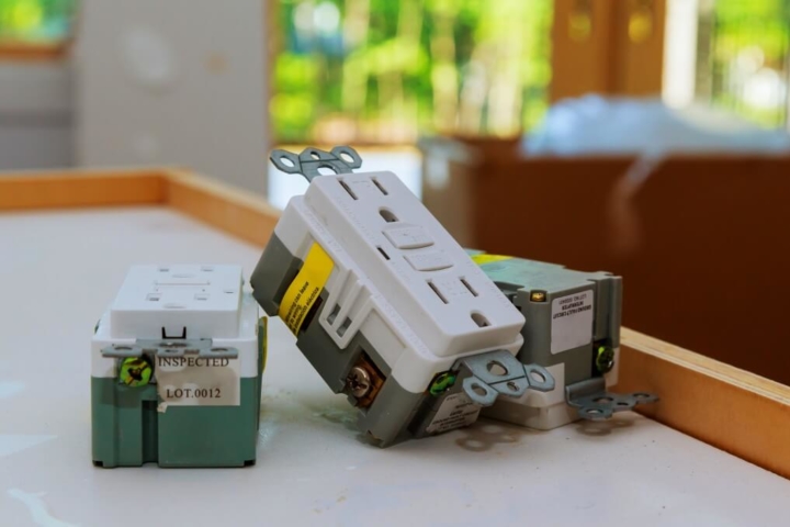
While there are many different types, here are the most common ones, which are found across most homes and offices:
- 120v Receptacles – These are easy to identify and come in a variety of colors. 120v plugs have three slots for connecting plugs – wider for neutral, narrower for hot and arched for ground
- 120/240v Receptacles – These have 4 slots that provide both 124v and 240v power – two for hot, one neutral and a ground
- 240v Receptacles – Unlike other 3-pronged receptacles, these have a grounding slot and 2 hot slots, which prevent other devices being plugged in and ensure adequate amperage
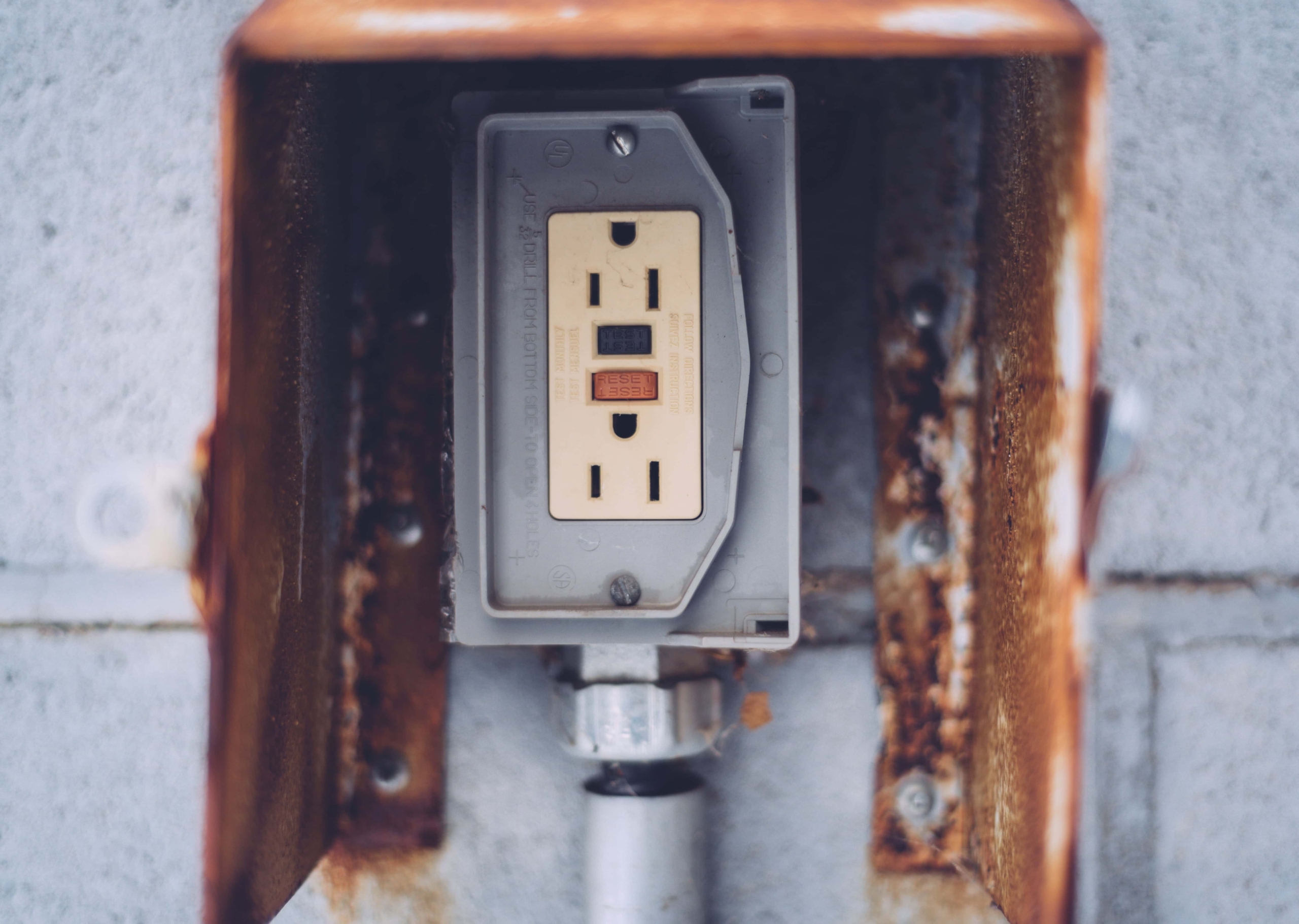
- GFCI – A Ground-Fault Circuit Interrupter or GFCI outlet is preferred for wet areas, since it reduces the risk of electrocution
Configurations Based on Socket-Blade Alignment
Image Source: Nooutage.com
Electrical Receptacle Nomenclature
The National Electrical Manufacturers Association (NEMA) defines a number of national configurations. It has established an alphanumeric nomenclature, which you should refer to before selecting a power outlet. The codification system has three sections:
-
- 2 – Ungrounded, Class II connections, max 15Vac
- 5 – Grounded, Class I connections, max 25Vac
- 6 – Grounded, Class I connections, max 250Vac
- 7 – Grounded, Class I connections, max 277Vac
- 8 – Grounded, Class I connections, max 480Vac
- 9 – Grounded, Class I connections, max 600Vac
- 14 – Four wire, single phase, three pole, max 125/250Vac
- 15 – Four wire, three phase, three pole, max 250Vac
- 16 – Four wire, three phase, three pole, max 480Vac
- 17 – Four wire, three phase, three pole, max 600Vac
- 21 – Five wire, three phase, four pole, max 120/208Vac
- 22 – Five wire, three phase, four pole, max 227/480Vac
- 23 – Five wire, three phase, four pole, max 357/600Vac
- [#x] – The third sections denotes the maximum rated amperage (typically 15,20,30,50 or 60 Amps), followed by an alphabet (“P” for a NEMA plug and “R” for a receptacle)
Other features are also included in the receptacle configuration, like AFCI (Arc-Fault circuit interrupter) and GFCI (Ground-Fault circuit interrupter).
Some International Electrical Receptacle Configurations
Apart from the standard NEMA configurations, many devices use different plug configurations. They are classified on the basis of the country or geographical region of origin, usually identified by an accompanying code:
- EU – Europe
- DE – Denmark
- FR – France, Algeria and Belgium
- IT – Italy
- SW – Switzerland
- AU – Australia
- UK – United Kingdom
- IS – Israel
- CH – China
- JA – Japan
- BR – Brazil
- AR – Argentina and many more
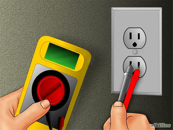
What Does a Receptacle Circuit Tester Check?
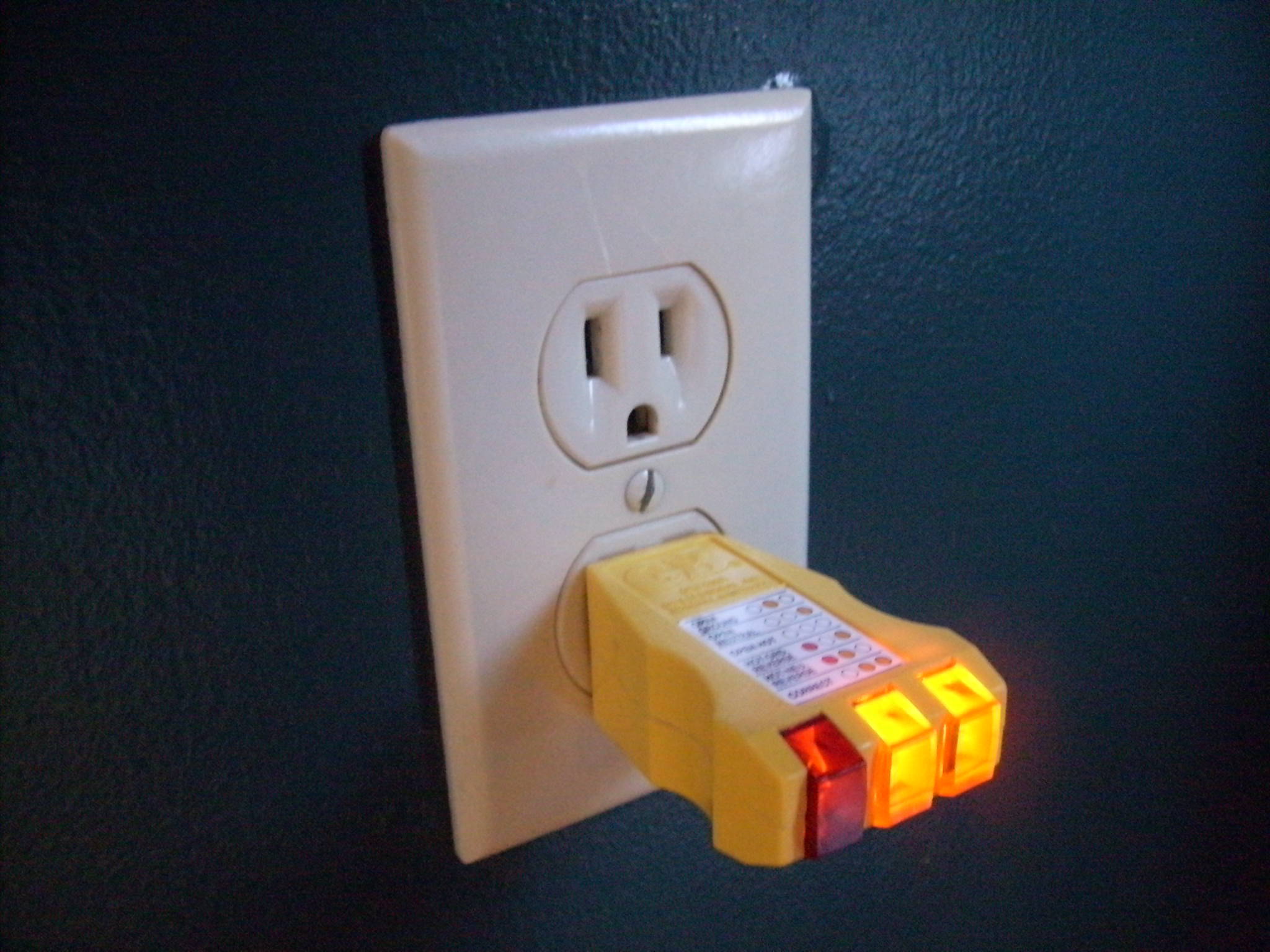
Image Source: icaschool.com
Improper wiring, loose connections and faulty or damaged receptacles pose a risk to life and property. A receptacle circuit tester can be used to perform various tests to check if a receptacle is installed correctly. Depending on the type of circuit tester, it can test other features as well, like:
- The connections of the neutral and live (hot) connection
- Presence of voltage (some can also test for the actual voltage levels)
- If the prongs are wired to the correct pole
- Whether a grounding pole is connected to the grounding system, and is functioning
- Proper connection between the housing of the receptacle and the ground
- Checking that ground and neutral are not cross-connected
If you’re using a three-light tester, it will not be able to detect some very dangerous situations. It cannot check for the ground and neutral connections being reversed and whether the ground and neutral are cross-connected.
Wiring a Receptacle Circuit
When you’re wiring highly loaded circuits, there are some situations where you can exceed the normal 80% load limit, but it depends on a variety of factor that you will need to ensure are met. As a precursor, you will have to know which device/s will be plugged into the receptacle, their load ratings and perhaps some manufacturer’s literature.
While it’s not recommended to run receptacles at loads close to their maximum rated capacity all the time, there are certain situations when you can. Before you do that, however, you should have a thorough understanding of receptacle configurations.
D&F Liquidators has been serving the electrical construction materials needs for more than 30 years. It is an international clearinghouse, with 180,000 square facility located in Hayward, California. It keeps an extensive inventory of electrical connectors, conduit fitting, circuit breakers, junction boxes, wire cable, safety switches etc. It procures its electrical materials supplies from top-notch companies across the globe. The Company also keeps an extensive inventory of electrical explosion proof products and modern electrical lighting solutions. As it buys materials in bulk, D&F is in a unique position to offer a competitive pricing structure. Besides, it is able to meet the most discerning demands and ship material on the same day.


